GRE Tunneling
GRE tunneling (Generic Routing Encapsulation).
Exam Topic
2.0 Virtualization
2.2 Configure and verify data path virtualization technologies
2.2.a GRE tunneling
Video Overview
Topic Overview
GRE stands for Generic Routing Encapsulation. What this is allows us to do is encapsulate packets inside another packet that then allows them to be forwarded over an IP network.
A good example of GRE tunneling is outlined below.
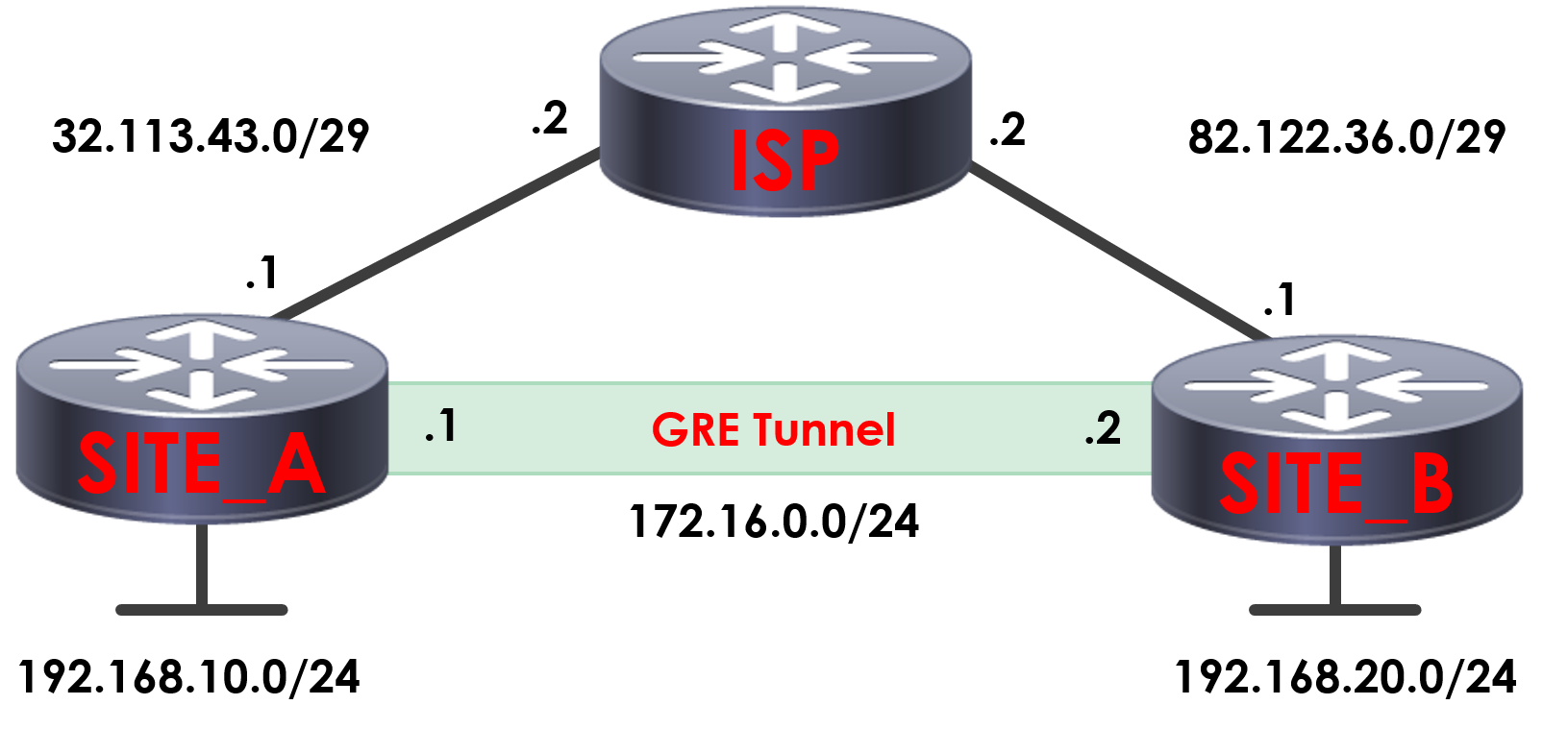
Here we’ve got two sites connected to the internet via an ISP, Site A and Site B. As both sites are connected to the internet and not directly connected via MPLS or other means – it means that at present, Sites A’s subnet of 192.168.10.0/24 is unable to route to Site B’s 192.168.20.0/24 across the internet to communicate or exchange routing information.
The reason for this is that we cannot route our private addresses across the internet. One of the ways of working around this could be to use GRE tunneling. What this will do is allow us to create a point to point connection between Site A and Site B. The GRE tunnel will allow the two sites to communicate with each other as if they where directly connected, forming a logical tunnel between the two and acting if they’re layer 2 adjacent. The traffic is now able to be routed across the internet as the traffic will be routed via a new GRE packet that includes the original packet within it, allowing it to be routed.
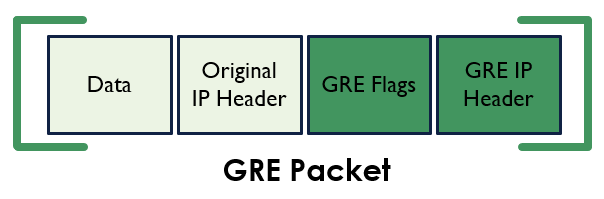
To give you an understanding of how this looks. Below displays an example of an original IP packet, before we’ve encapsulated it with GRE.

This is then how the packet would then look once it’s been encapsulated within GRE.
Benefits of GRE
GRE tunneling provide us a number of benefits, including:
Downsides of GRE
Despite all of the benefits GRE tunneling provide, there are unfortunately some downsides:
Configuration
So now we understand GRE tunneling, lets take a look at how we can configure them on our Cisco devices.
We’re going to be using the example we looked at earlier for our GRE lab. As you can see, we have two sites connected to our ISP, both with public IP addresses at each location. Each of our locations has its own network. At Site A we’re using 192.168.10.0/24 and at Site B we’re using 192.168.20.0/24.
What we’re going to do is create a GRE tunnel between the two sites to connect them and allow them to act as if they’re directly connected. For the tunnel itself we need an IP for each end on the same subnet. As such, in this scenario we’re going to be using 172.16.0.0/24.
The first thing we need to do is configure our interfaces on the following routers:
ISP#configure terminal
ISP(config)#interface Serial2/0
ISP(config-if)#ip address 32.113.43.2 255.255.255.248
ISP(config-if)#no shutdown
ISP(config-if)#
exit
ISP(config)#interface Serial2/1
ISP(config-if)#ip address 82.122.36.2 255.255.255.248
ISP(config-if)#no shutdown
SITE_A#configure terminal
SITE_A(config)#interface Serial2/0
SITE_A(config-if)#ip address 32.113.43.1 255.255.255.248
SITE_A(config-if)#no shutdown
SITE_A(config-if)#exit
SITE_A(config)#interface loopback 0
SITE_A(config-if)#ip address 172.16.0.1 255.255.255.0
SITE_A(config-if)#exit
SITE_A(config)#ip route 0.0.0.0 0.0.0.0 32.113.43.2
SITE_B#configure terminal
SITE_B(config)#interface Serial2/1
SITE_B(config-if)#ip address 82.122.36.1 255.255.255.248
SITE_B(config-if)#no shutdown
SITE_B(config-if)#exit
SITE_B(config)#interface loopback 0
SITE_B(config-if)#ip address 172.16.0.2 255.255.255.0
SITE_B(config-if)#exit
SITE_B(config)#ip route 0.0.0.0 0.0.0.0 82.122.36.2
Now that we’ve got our basic configuration on our devices, the first thing we need to do is confirm we can route between Site A and Site B over the internet.
SITE_A#ping 82.122.36.1
Type escape sequence to abort.
Sending 5, 100-byte ICMP Echos to 82.122.36.1, timeout is 2 seconds:
!!!!!
Success rate is 100 percent (5/5), round-trip min/avg/max = 20/24/1 ms
Now we’ve confirmed routing between our public interfaces from Site A to Site B, lets get into the configuration of our GRE tunnel.
SITE_A#configure terminal
SITE_A(config)#interface tunnel 1
SITE_A(config-if)#tunnel source Serial2/0
SITE_A(config-if)#tunnel destination 82.122.36.1
SITE_A(config-if)#ip address 172.16.0.1 255.255.255.0
SITE_B#configure terminal
SITE_B(config)#interface tunnel 1
SITE_B(config-if)#tunnel source Serial2/2
SITE_B(config-if)#tunnel destination 32.113.43.1 SITE_B(config-if)#ip address 172.16.0.2 255.255.255.0
Now that’s been completed, that’s all of the configuration required for our GRE tunnel.
As such, the next thing we need to do is confirm our GRE tunnel is now up and active.
SITE_B#show interface tunnel 1
Tunnel1 is up, line protocol is up
Hardware is Tunnel
Internet address is 172.16.0.2/24
MTU 1514 bytes, BW 9 Kbit/sec, DLY 500000 usec,
reliability 255/255, txload 1/255, rxload 1/255
Encapsulation TUNNEL, loopback not set
Keepalive not set
Tunnel source 82.122.36.1 (Serial2/1), destination 32.113.43.1
Tunnel protocol/transport GRE/IP
Key disabled, sequencing disabled
Checksumming of packets disabled
Tunnel TTL 255
Fast tunneling enabled
Tunnel transmit bandwidth 8000 (kbps)
Tunnel receive bandwidth 8000 (kbps)
Last input 00:00:15, output 00:00:15, output hang never
Last clearing of “show interface” counters never
Input queue: 0/75/0/0 (size/max/drops/flushes); Total output drops: 0
Queueing strategy: fifo
Output queue: 0/0 (size/max)
5 minute input rate 0 bits/sec, 0 packets/sec
5 minute output rate 0 bits/sec, 0 packets/sec
5 packets input, 620 bytes, 0 no buffer
Received 0 broadcasts, 0 runts, 0 giants, 0 throttles
0 input errors, 0 CRC, 0 frame, 0 overrun, 0 ignored, 0 abort
5 packets output, 620 bytes, 0 underruns
0 output errors, 0 collisions, 0 interface resets
0 unknown protocol drops
0 output buffer failures, 0 output buffers swapped out
We can see here that the interface we created it in an up state and is a GRE tunnel.
The next thing we need to do is ping the remote end of the GRE tunnel to confirm we have routing via the GRE tunnel.
SITE_B#ping 172.16.0.1
Type escape sequence to abort.
Sending 5, 100-byte ICMP Echos to 172.16.0.1, timeout is 2 seconds:
!!!!!
Success rate is 100 percent (5/5), round-trip min/avg/max = 36/42/44 ms
If we do a traceroute from Site B across to Site A, you’ll see that we only have 1 hop
SITE_B#traceroute 172.16.0.1
Type escape sequence to abort.
Tracing the route to 172.16.0.1
1 172.16.0.1 40 msec 44 msec 40 msec
From the perspective of our site routers, they act like they’re directly connected – this is where it gets the tunneling name from.
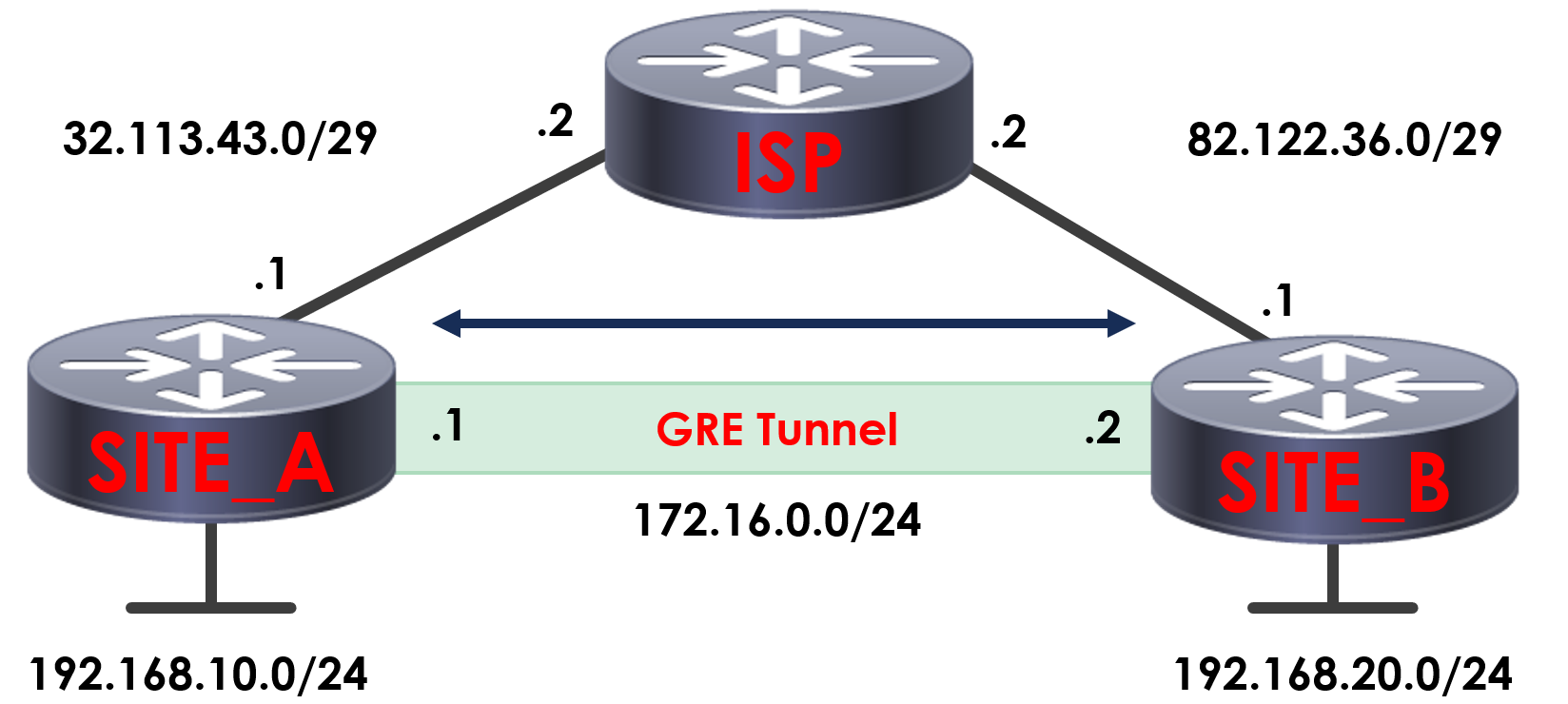
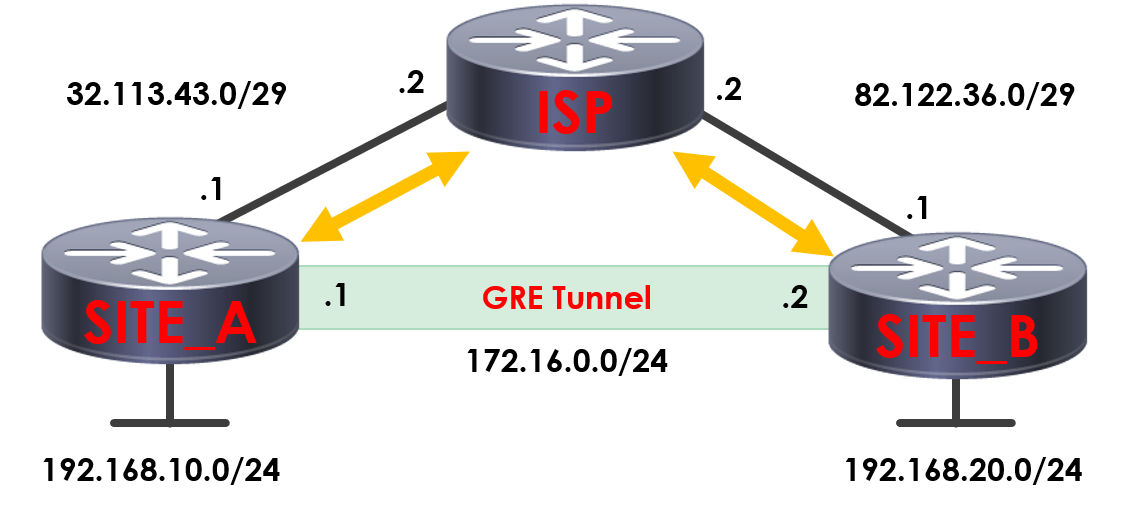
In reality, the packets are routing via the ISP between the sites – but encapsulated within the GRE packets, as we discussed earlier.
ow we’ve got our tunnel up between Site A and Site B, we still cannot route between the local subnets – which is what we’re trying to achieve.
SITE_B#traceroute 172.16.0.1
Type escape sequence to abort.
Tracing the route to 172.16.0.1
1 172.16.0.1 40 msec 44 msec 40 msec
SITE_B#show ip route
Codes: C – connected, S – static, R – RIP, M – mobile, B – BGP
D – EIGRP, EX – EIGRP external, O – OSPF, IA – OSPF inter area
N1 – OSPF NSSA external type 1, N2 – OSPF NSSA external type 2
E1 – OSPF external type 1, E2 – OSPF external type 2
i – IS-IS, su – IS-IS summary, L1 – IS-IS level-1, L2 – IS-IS level-2
ia – IS-IS inter area, * – candidate default, U – per-user static route
o – ODR, P – periodic downloaded static route
Gateway of last resort is 82.122.36.2 to network 0.0.0.0
172.16.0.0/24 is subnetted, 1 subnets
C 172.16.0.0 is directly connected, Tunnel1
82.0.0.0/29 is subnetted, 1 subnets
C 82.122.36.0 is directly connected, Serial2/1
C 192.168.20.0/24 is directly connected, Loopback0
S* 0.0.0.0/0 [1/0] via 82.122.36.2
You can see here if we try to ping the subnet at Site B from Site A, our packets are undeliverable. The reason for this is that our routers would try to route this via their default static route, which is via our ISP.
Now we’ve got our GRE tunnel up and active, we’ve got two ways of routing between the subnets at both of our sites.
Create static routes for the subnets to route via the GRE tunnel. Setup a routing protocol between Site A and Site B, via the GRE tunnel.
As GRE tunnels allow the use of multicast and broadcast traffic, one of the benefits of using GRE tunnels is that we can use routing protocols across it. As such, we’ll setup some basic EIGRP configuration between Site A and Site B.
SITE_A#configure terminal
SITE_A(config)#router eigrp 10
SITE_A(config-router)#network 192.168.10.0 0.0.0.255 SITE_A(config-router)#network 172.16.0.0 0.0.0.255
SITE_B#configure terminal
SITE_B(config)router eigrp 10
SITE_B(config-router)#network 192.168.20.0 0.0.0.255 SITE_B(config-router)#network 172.16.0.0 0.0.0.255
We can see now, that our two routers have formed an EIGRP neighbour relationship across the GRE tunnel.
SITE_A#show ip eigrp neighbors
IP-EIGRP neighbors for process 10
H Address Interface Hold Uptime SRTT RTO Q Seq
(sec) (ms) Cnt Num
0 172.16.0.2 Tu1 10 00:02:43 143 5000 0 3
What should now have also learned the local subnets across the tunnel, via EIGRP.
Let’s take a look at the routing table on Site A.
SITE_A#show ip route
Codes: C – connected, S – static, R – RIP, M – mobile, B – BGP
D – EIGRP, EX – EIGRP external, O – OSPF, IA – OSPF inter area
N1 – OSPF NSSA external type 1, N2 – OSPF NSSA external type 2
E1 – OSPF external type 1, E2 – OSPF external type 2
i – IS-IS, su – IS-IS summary, L1 – IS-IS level-1, L2 – IS-IS level-2
ia – IS-IS inter area, * – candidate default, U – per-user static route
o – ODR, P – periodic downloaded static route
Gateway of last resort is 32.113.43.2 to network 0.0.0.0
32.0.0.0/29 is subnetted, 1 subnets
C 32.113.43.0 is directly connected, Serial2/0
C 192.168.10.0/24 is directly connected, Loopback0
172.16.0.0/16 is variably subnetted, 2 subnets, 2 masks
C 172.16.0.0/24 is directly connected, Tunnel1
D 172.16.0.0/16 is a summary, 00:01:10, Null0
D 192.168.20.0/24 [90/297372416] via 172.16.0.2, 00:00:47, Tunnel1
S* 0.0.0.0/0 [1/0] via 32.113.43.2
Here we can see now that we’ve learned Site B’s 192.168.20.0/24 subnet across the GRE tunnel via EIGRP.
If I do a ping to this from Site A, we can confirm we can now route to site B’s local subnet across the tunnel.
SITE_A#ping 192.168.20.254
Type escape sequence to abort.
Sending 5, 100-byte ICMP Echos to 192.168.20.254, timeout is 2 seconds:
!!!!!
Success rate is 100 percent (5/5), round-trip min/avg/max = 40/42/44 ms