Performing Predictive Wireless Site Surveys
Predictive site surveys are key to helping you design your wireless network. In this lesson, we’ll take a look at how to perform predictive wireless surveys and how to interpret the output.
Exam Topic
1.0 Wireless Site Survey
1.6 Perform a predictive site survey
Predictive Site Survey Overview
Predictive site surveys are virtual surveys that can be completed off-site. The software tools used to produce the predictive survey results will require the following items:
The predictive wireless surveys are produced by wireless engineers by inputting a number of different variables. The software then uses these variables to determine the following information:
A number of tools are available on the market to assist with the predictive survey. These tools include:
Survey Process
To help you understand the predictive survey process a little easier, let’s go through the process. For our example, I’ll be using Ekahau Pro.
It’s worth noting that this is not intended to be an in-depth overview. Instead it should be used to gain an insight into the process. The Ekahau Pro software could be broken down into it’s own course itself.
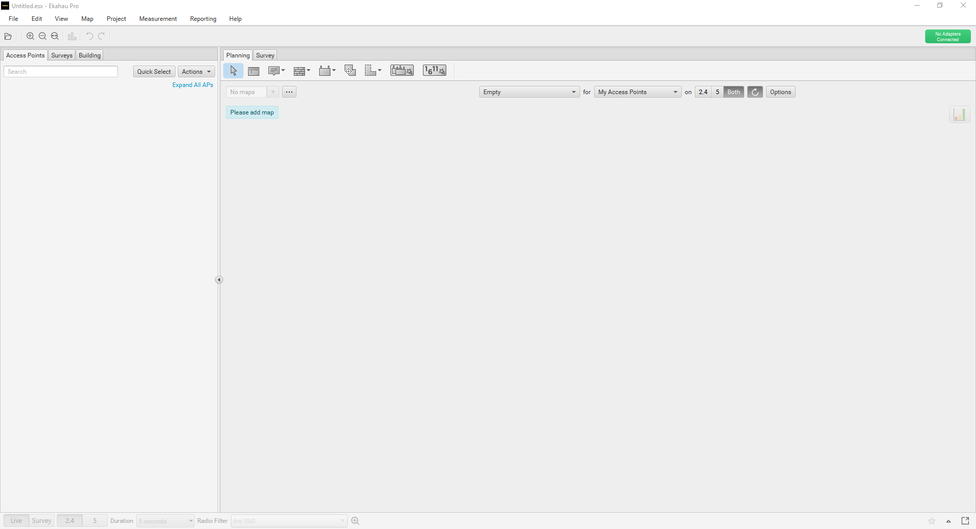
1. Open Ekahau.
We’ll start by opening the Ekahau Pro software.
2. Upload Floorplans
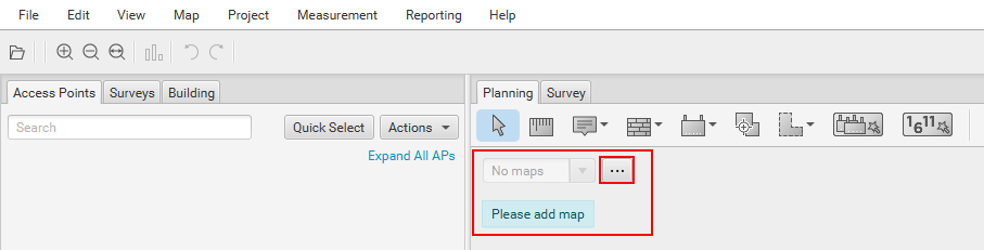
Within Ekahau, floorplans are known as maps. You’ll notice that the first thing it asks us to do is ‘Please add map‘.
We can add the floorplans by pressing the ‘…‘ icon here.
You then have the ability to upload your floor plans in the following format:
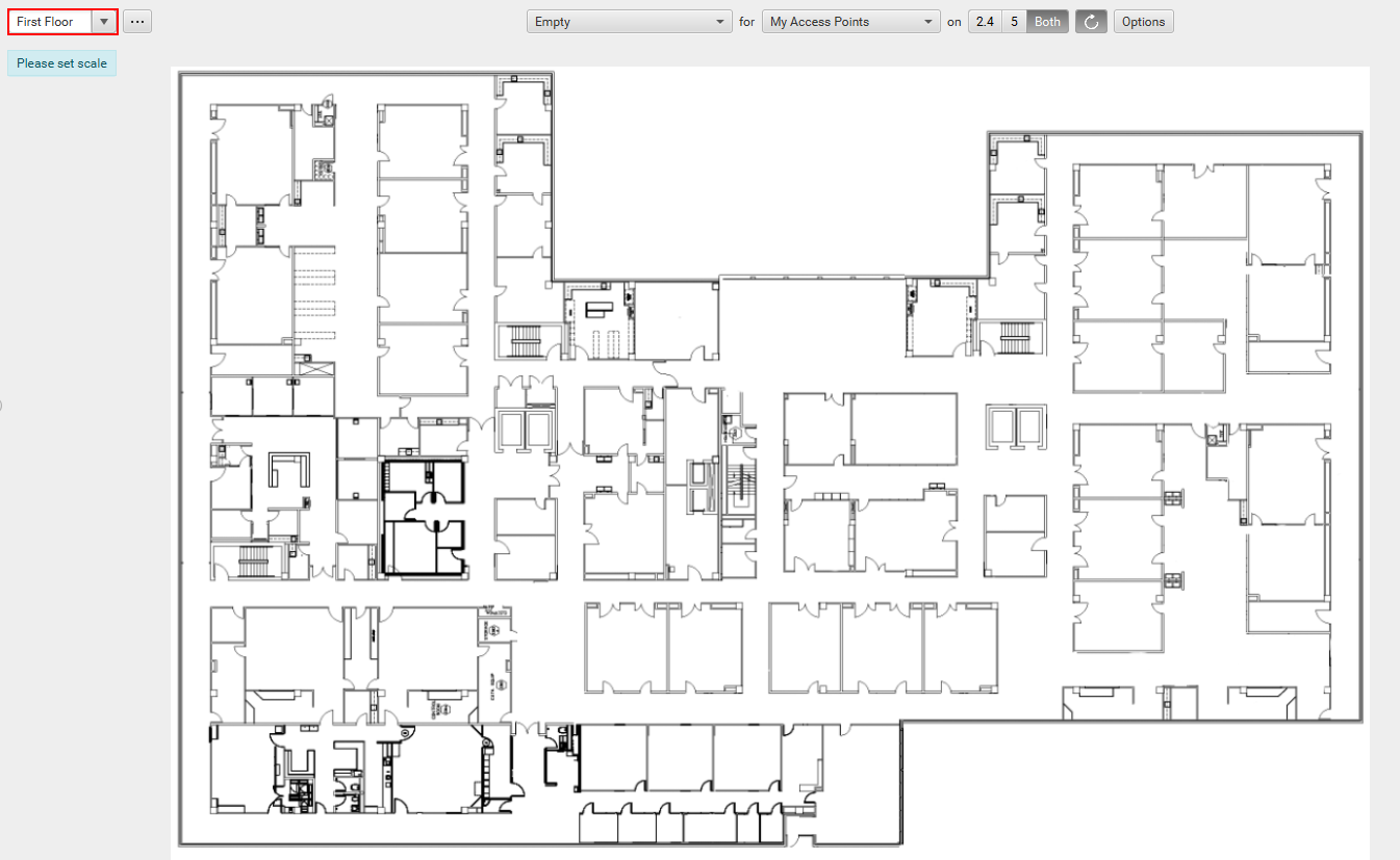
For our example, I’ve uploaded a demo floor plan provided by Ekahau. In addition to this, I also recommend providing your floor plan a friendly name. In our example, I’ve called mine ‘First Floor‘.
3. Set Floorplan Scale
In order for Ekahau to operate correctly, we need to tell it the scale of our drawings. It’s important to ensure that the scale we enter is 100% accurate else our predictive survey will be inaccurate.
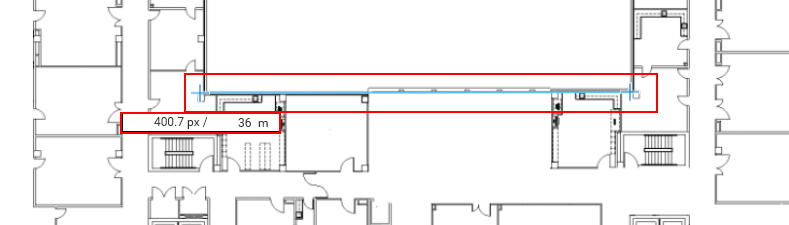
We can set the scale of our floorplan by selecting the rule icon on the bar at the top.
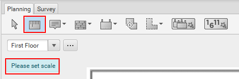
All we then have to do is drag and draw the scale onto our floor plan. In our example, the wall outlined in blue is 36m long. Ekahau will then work our the scale for the rest of the floorplan.
4. Draw our Material Attenuation
At this point, Ekahau only knows the scale of our drawing. It has no idea on where the walls are located, what material they’re made of etc. As such, we need to input this information now.
This can be a tedious process if your floorplans have a number of floors or walls. As such, it’s best practice if possible to get hold of CAD drawings for the location. Ekahau then allows you to speed this process up by applying materials to layers
within the CAD file.
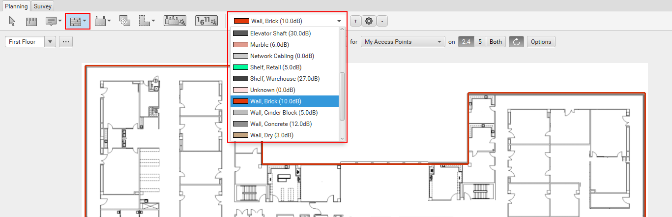
We can add our materials by selecting the ‘wall‘ icon here:
You’ll then notice a drop down menu allowing us to select our material. On our example, I’ve drawn the outer walls as brick. Let’s draw in all of the walls in our example and continue.
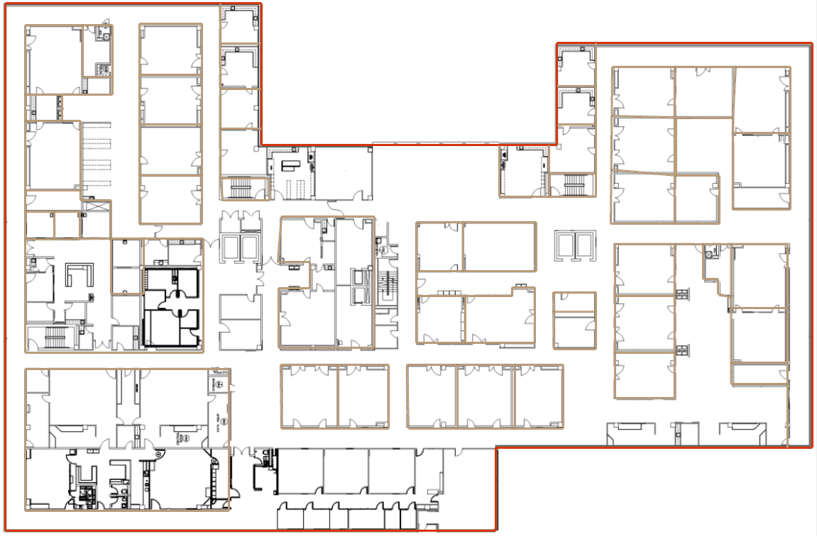
I’ve drawn the majority of the walls in for our example, just to provide some context. It’s important to accurately capture your materials correctly when doing this else it can widely affect your wireless design. Either meaning you under or over allocate the amount of APs required.
5. Set Coverage Requirements
The next step is to tell Ekahau the following information:
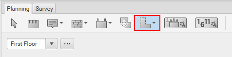
We can do this by selecting the coverage tool under the planning tools.
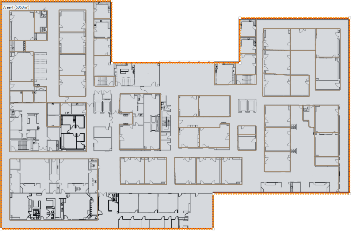
On our floor plan, we then need to draw out the areas that require wireless coverage. If we were doing this for real, it’s best practice to break down the coverage areas as much as possible. The reason for this is that allows you to accurately provide
Ekahau the variables we discussed previously.
In order to keep this brief, we’ll set our coverage area to cover the whole floorplan, however this isn’t recommended when completing this for real. This is purely for demonstration purposes.
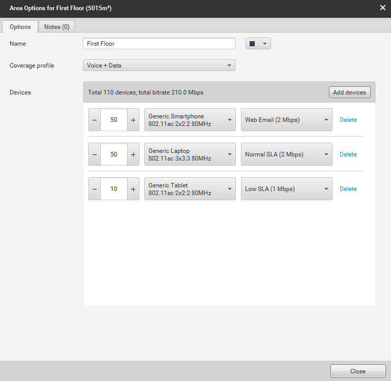
Once our areas have been drawn out, we can edit the following parameters:
This can be accessed by right clicking the area and selecting ‘Edit Area‘.
Let’s go through our example.
First of all, I’ve given our area a name. I’ve called ours First Floor. This makes it easier for us to understand which areas are for what – especially in larger projects.
Next, we’ll be using the Voice + Data coverage profile as our clients will be using both voice and data in the environment. This is a default template provided by Ekahau and should be amended to your design requirements.
Finally, I’ve added the devices that will be using wireless in our selected area. For our example, I’ve added:
50x Generic Smartphones that will be using an average of 2Mbps each.
50x Generic Laptops that will be using an average of 2Mbps each.
10x Tablets that will be using an average of 1Mbps each.
Again, these are default profile and should be fine-tuned to the device specifications within your environment. The design should also be designed for the worst-case scenario with regards to the amount of devices connecting to the network.
For example, if there’s a chance we might get 100 laptops connecting in this area, I should design the wireless network for 100 laptops connecting.
6. Auto-Plan AP Placement
The final thing for us to do is get Ekahau to automatically place APs on the map. The software will place the APs on our floor plan where it thinks best. It calculates this based on the following criteria:
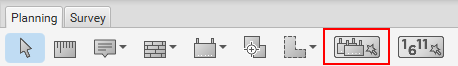
To do this, we’ll select the auto-plan feature here:
We’re then prompted for some more information about our wireless environment. This includes:
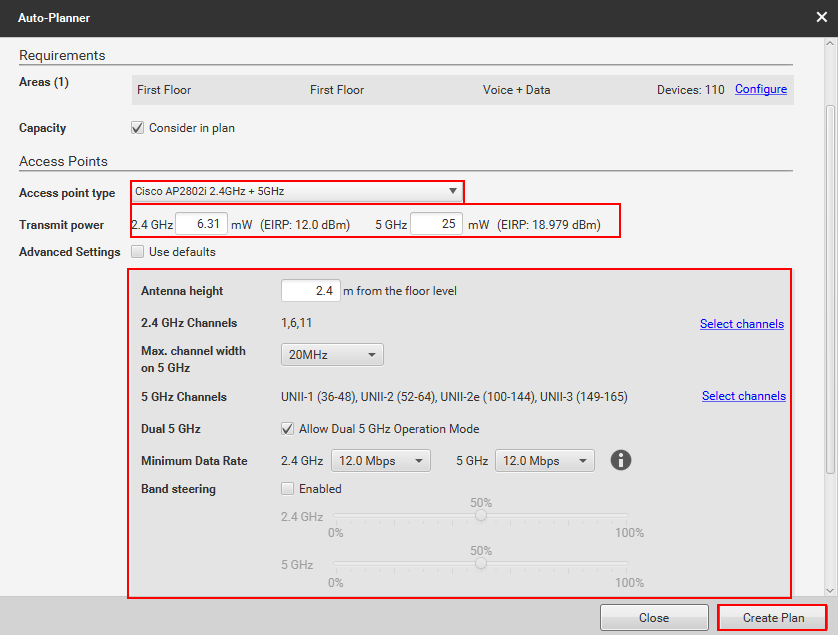
Once you’ve configured the required parameters, we’ll press Create Plan.
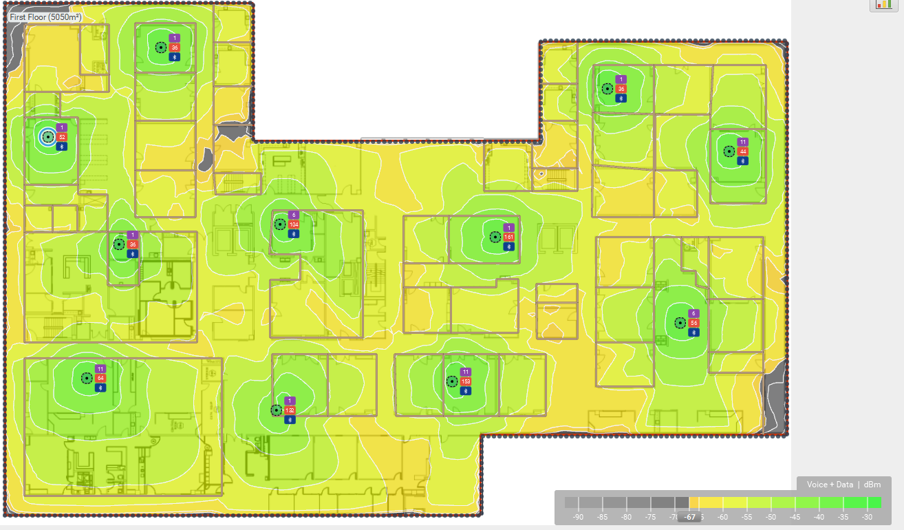
Based on the requirements and information we’ve provided Ekahau, it then predicts the following:
You’ll notice I say “Rough” AP Placement. The reason for this is the predictive survey should be followed up with an APoS/Pre-deployment survey. This then confirms that the results provided by Ekahau match what you’ll expect in the real world.