Powering APs
As we’ve already discussed, there are a number of ways of powering APs. In this lesson, we’ll be looking at using PoE and power injectors to power your APs.
Exam Topic
2.0 Wired and Wireless Infrastructure
2.1 Determine physical infrastructure requirements such as AP power, cabling, switch port capacity, mounting and grounding
Overview
Can you imagine having to get an electrician to run power to each AP in your deployment? It would be a nightmare and cost a fortune.
Thankfully, we have the ability to power our APs using existing structured cabling using Power over Ethernet (PoE).
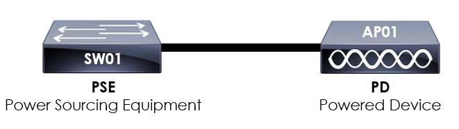
Let’s take a look at our example above to understand how it works.
Here you can see an AP connected to our switch. Our AP is known as the Powered Device (PD) as it’s the device being powered.
The switch in our example is known as the Power Sourcing Equipment (PSE) as it’s providing power to our powered device.
There are currently five standards of PoE, each with different capabilities;
The main differences between the PoE standards is the amount of power they provide. We’ll cover each PoE standard in detail later in the lesson.
In order for the switch to provide PoE to the devices, it must be a PoE compatible device. Different switches support different PoE capabilities so it’s important to check which standard of PoE your switch supports.
In addition to this, depending on the switch model, switches can only power a number of devices up to a certain Watt.
To provide some context, I’ve got a Cisco WS-C2960X-24PS-L. Connected to the switch, I’ve got a Cisco AP connected.
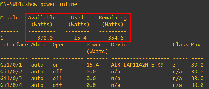
We can view the available Watts on our switch by running the show power inline command. In our example you can see that we have 370.0 Watts of power available for PoE compatible devices. Of this available power,
we’ve used 15.4 Watts.
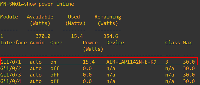
From the show power inline output, we can also see which of our interfaces are powering PoE compatible devices. In our example, Gi1/0/1 is providing 15.4 Watts of power to an AIR-LAP1142N AP.
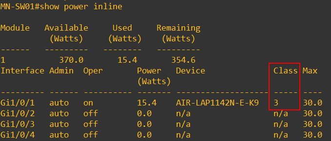
Notice that our device connected to Gi1/0/1 has a class of 3? What does this mean?
Not all devices that requires power via PoE require the same power (Watts) to operate. As such, both the PSE and PD can negotiate a power classification. This classification is used to identify
how much power the device requires.
If you think about it, it makes sense. We wouldn’t want our switch to provide or allocate more power to a PD than what’s required. This in turn means that we’ve got more available power for other PoE compatible devices.
If power classification is not supported by either the PSE or PD, all PoE devices connecting will be provided the maximum power available on the PSE.
PoE (802.3af)
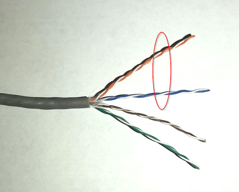
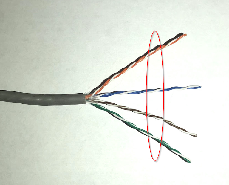
802.3af was the original PoE standard. It works by providing power over two pairs of a structured cable. This is shown on the figure below.
The original PoE standard can be used to provide up to 15.4W of power to a powered device. Unfortunately, due to power dissipation on the cable, only 12.95W is available to the device.
An easy way to remember this is:
Maximum power provided by PoE port: 15.4W
Maximum power received by powered device: 12.95W
It’s worth noting, the cable needs to be of Catagory 5E or above for 802.1af to be supported
PoE+ (802.3at)
As devices required greater power to operate, an improved revision of PoE was ratified. This is known as PoE+ and is standardised under 802.3at.
Like the original PoE standard, PoE+ works by providing power to the PD via two pairs of a structured cable.
The main advantage of PoE+ is that it can now provide up to 30W of power. As before, there is loss of power on the cable. Due to this 25.5W of power is received by the PD.
An easy way to remember this is:
Maximum power provided by PoE+ port: 30W
Maximum power received by powered device: 25.5W
It’s worth noting, the cable needs to be of Catagory 5E
or above for 802.1at to be supported
PoE++ (802.3bt)
With the ease of providing power to devices throughout the network with structured cabling, more and more devices have began to support PoE capabilities. With this, there has been a requirement for higher power draw to a PD. As such, a further standard
was developed known as PoE++ (802.3bt).
As additional power draw is required by devices, instead of delivering power over just two pairs, PoE++ uses all four.
With PoE++, it can now provide 100W of power. As with the previous two standards, there is loss power power on the cable. Due to this, a maximum of 71W of power can be received by the PD.
An easy way to remember this is:
Maximum power provided by PoE+ port: 100W
Maximum power received by powered device: 71W
UPOE
Unlike the previous examples that we’ve looked at which are standards based, the following UPOE methods are Cisco Proprietary. UPOE stands for Universal Power Over Ethernet.
Like PoE++, UPOE is utilises all four pairs of the cable. By splitting the cables into two groups of 2 pairs, each group of 2 pairs can carry 30W.
UPOE has the capability of providing 60W of power. As with the previous open standards, there is loss power power on the cable. Due to this, a maximum of 51W of power can be received by the PD.
An easy way to remember this is:
Maximum power provided by PoE+ port: 60W
Maximum power received by powered device: 51W
UPOE+
Like UPOE, UPOE+ is a Cisco Proprietary protocol.
Like PoE++ and UPOE, UPOE+ utilises all four pairs of the cable. By splitting the cables into two groups of 2 pairs, each group of 2 pairs can carry 45W .
UPOE+ has the capability of providing 90W of power. As with the previous open standards, there is loss power power on the cable. Due to this, a maximum of 71W of power can be received by the PD.
An easy way to remember this is:
Maximum power provided by PoE+ port: 90W
Maximum power received by powered device: 71W