Radio Resource Management (RRM) Overview
RRM is usually just left to ‘do its thing‘, however it’s a key topic to understand and tweak accordingly. In this lesson, we’ll understand how RRM works and continually monitors your wireless network.
Exam Topic
2.0 Wired and Wireless Infrastructure
2.3 Design radio management
2.3.a RRM
Overview
Radio Resource Management (RRM) is a feature built into Cisco wireless controllers that continuously monitors your wireless RF environment.
If you imagine your enterprise wireless environment, there are always multiple variables that are constantly changing.
These include;
Can you imagine spending day after day constantly tweaking the wireless network after every change of event or eventuality? Your job would become quite dull and miserable.
Thankfully, Cisco wireless controllers have a number or tools and functions to automatically identify and resolve any issues it detects.
The tools that we’ll be looking all fall under the radio resource management (RRM) umbrella. These include:
It’s important to note, the RRM tools are not designed to fix underlying issues with the wireless design. Instead, they are designed to keep your wireless network at optimal performance.
You might be thinking, how does the controller know what settings to tweak in our environment?
In order for RF data to be collected, a protocol called Neighbour Discovery Protocol (NDP) is used. The NDP protocol is then used to build a “map” of your RF environment.
The RRM functions can be enabled in one of two ways;
Configuring the RRM settings is great if all the APs are located within a single physical area. The problem is, in a majority of cases, APs are spread across multiple geographical areas.
If we want to apply specific RRM parameters to certain APs, we can make use of RF Profiles.
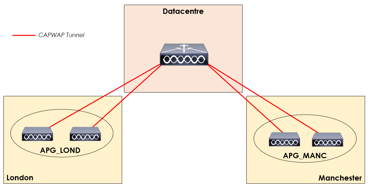
In our topology, we’ve got two remote locations; London and Manchester. Each location has two APs associated.
Within the WLC we can group our APs into AP groups. With our topology, we’ve got two AP groups; APG_LOND and APG_MANC.
To these groups we can then apply specific RRM parameters using configured RF Profiles.
Radio Resource Monitoring (RRM)
When an AP is not serving clients, it will go away off-channel to scan other channels. This is done to monitor all other channels for any noise or interference.
Transmit Power Control (TPC)
The WLC can tweak the transmit power of APs based on the environments RF conditions.
For example, a wireless controller can lower the transmit power of an AP to reduce interference. Alternatively, additional coverage may be required. In which case, the controller will increase the transmit power of an AP.
We’ll go into TPC in more depth in our upcoming lesson
here.
Dynamic Channel Assignment (DCA)
Our RF environment is constantly changing. What happens if a rogue AP starts broadcasting on channel our AP is using? Alternatively, we may be experiencing interference from non-802.11 devices.
DCA is used to determine the optimal AP channel, based on a number of variables collected by the AP. If a more optimal (better) channel is available, our WLC can move the AP to a different channel automatically. In turn, reducing the disruption
to wireless clients.
We’ll go into DCA in more depth in our upcoming lesson here.
Coverage Hole Detection & Correction (CHDC)
When clients connected to a wireless network have issues with roaming, how do we detect it? Chances are, we’d only detect the issue if wireless users detect and report it. But what if they don’t?
CHDC can be used for two functions. Firstly, to alert the network administrator of areas of weak coverage. Secondly, areas of poor coverage can be corrected by the controller by increasing the transmit power on an AP.
We’ll go into CHDC in more depth in our upcoming lesson here.
Flexible Radio Assignment (FRA)
High-density environments are becoming more common practice in wireless environments. Cisco APs by default will disable redundant 2.4GHz radios. FRA is designed to maximise the investment in the AP by utilising these radio for other purposes.
For example, FRA could change the antenna to operate on another 5GHz channel. When this occurs, the AP will operate on two separate 5GHz channels. Thus, increasing the amount of clients that can connect to a single AP.
Alternatively, our redundant antenna can be operate in monitor mode, depending on the network conditions.
We’ll go into FRA in more depth in our upcoming lesson here.
Receive Start of Packet (RX-SOP)
In environments with lots of noise and interference, RX-SOP tells the AP antenna what to demodulate and decode.
A threshold is set on an AP. Any frames above the threshold will be ignored by the AP and treated as noise.
RX-SOP can then be used to increase the wireless performance for environments with a high amount of co-channel interference.
We’ll go into RX-SOP in more depth in our upcoming lesson
here.