Transmit Power Control (TPC)
One of the functions that makes up the RRM operations is Transmit Power Control (TPC). In this lesson, we’ll be taking a closer look at the TPC algorithm and how it works.
Exam Topic
2.0 Wired and Wireless Infrastructure
2.3 Design radio management
Overview
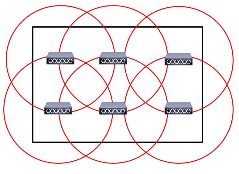
APs can broadcast and operate using a number of different power levels. The higher the power is set on our APs, the bigger our coverage cell. Due to this, the transmit power configured on APs needs to be managed to reduce co-channel
interference.
Can you imagine having to manage the power on each AP manually? Even then, having to find the right transmit power for your environment? It would be a nightmare… Thankfully, TPC (Transmit Power Control) can
manage this for us automatically.
TPC is an algorithm that runs on our wireless controller every 10 minutes by default. The main aim is to set an APs transmit power to its optimal value. This value will provide the best performance to clients
whilst avoiding interference with other APs.
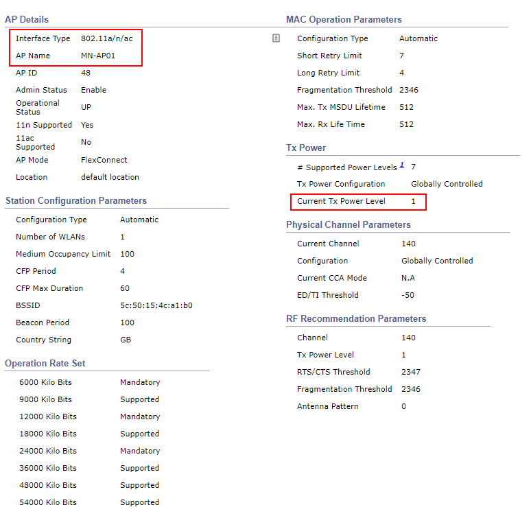
As the AP will most likely have an antenna on the 2.4GHz and 5Ghz bands, TPC will run independently. There will be one transmit power set for the 2.4GHz radio and another for the 5GHz radio.
As the wireless controller has no idea how our wireless network is setup, NDP (Neighbour Discovery Protocol) is used to build the topology. Using the NDP frames, our WLC will
The WLC looks for APs that can hear each other at -70dBm or greater. In addition for this, in order for the TPC algorithm to operate, the AP must be able to hear an additional 3 APs.
We might have scenarios where we have a number of wireless controllers within our deployment. If this is the case, the controller allocated as RF group leader will run the TPC algorithm.
Now that you understand how TPC operates, let’s take a look at how the algorithm works. Our wireless controller will use the following criteria to determine if a TPC change is required:
1. Can the AP detect three other APs at -70dBm?
2. Use the following formula to determine the transmit power:
Tx_Max + (Tx Power Control threshold – RSSI of 3rd highest neighbour)
In order to minimise potential disruption, RRM will only make gradual changes to the transmit power. As such, RRM will only increase or decrease the power by 3dB (half or double the transmit power).
Configuration
In most cases, TPC doesn’t require any configuration to work. There might however be situations where the TPC algorithm needs to be tweaked.
TPC configuration can applied using either of the following options:
It’s worth noting that some TPC parameters can only be configured globally. This includes;
Global Configuration:
Remember that the TPC algorithm runs independently on each 802.11 band. As such, we have a global TPC configuration for the 2.4GHz band (802.11b/g/n/ax) and one for the 5GHz band (802.11a/n/ac/ax).
The 2.4GHz global configuration can be configured by navigating to:
WIRELESS > 802.11b/g/n/ax > RRM > TPC
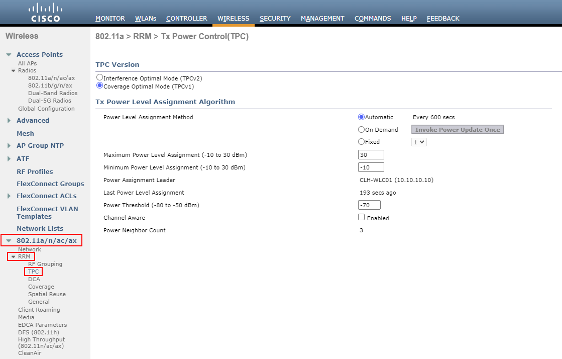
The 5GHz global configuration on the other hand can be configured by navigating to:
WIRELESS > 802.11a/n/ac/ax > RRM > TPC
There are a number of configurable options available to TPC global configuration. This includes:
TPC Version:
There are two methods of TPC available:
Unless you have a specific reason otherwise, it’s recommended to use the default TPCv1 – Coverage Optimal Mode.
TPC Run Method:
TPC can run using one of the following methods:
Minimum / Maximum Power Level Assignment:
These thresholds can be used to set the minimum or maximum amount of power that APs can use within the environment.
Power Threshold:
Finally, this is the cutoff used by RRM to determine whether it should reduce an APs power.
An increase of the power threshold will cause the AP to operate at higher transmit power rates.
A decrease of the threshold on the other hand will cause the AP to operate at lower transmit power rates.
RF Profile:
Alternately, we can control TPC parameters using RF profiles. Our RF profile can then be applied to AP groups to control TPC on specific APs.
In our example, I’ve created an RF profile called MN_RF-Profile-2.4GHz.
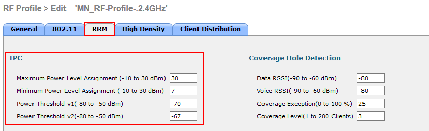
The TPC parameters can be configured under the RRM tab of our RF profile.
We can then amend the following configuration parameters: