Wireless Mobility Concepts
In a wireless environment with multiple APs, roaming takes place all the time. Roaming occurs when a client roams from one AP to another.
In this lesson, we’ll be taking a look at types of roaming events that can take place within our wireless network.
Exam Topic
3.0 Mobility
3.1 Design mobility groups based on mobility roles
Video Overview
Overview
Mobility roaming occurs within our wireless environment when a client roams between our APs. This occurs all the time within wireless environments when a client moves from one AP to another.
Along with this, wireless networks can be deployed in a number of different topologies. Depending on our wireless design, there are a number of different roaming events that can occur;
As we proceed through the lesson, we’ll take a look at the each roaming event, how it occurs and what takes place in the background.
Intracontroller Roaming
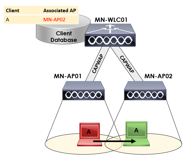
We’ll start with intracontroller roaming. This occurs when a client roams between APs associated to the same controller.
As you can see from our topology above, we’ve got two APs; MN-AP01 and MN-AP02. These APs are then associated to a single WLC; MN-WLC01.
The WLC then maintains a client database that contains information on how to reach each client. When Client A roams from MN-AP01 to MN-AP02, the WLC will update its client database to update how it reaches Client A.
The intracontroller roaming method is the most simplest method of roaming.
Intercontroller Roaming – Layer 2
Intercontroller roaming occurs when a client roams between APs associated to two different WLCs. For the roam to be classed as a layer 2 intercontroller roam, both controllers will have an interface in the clients subnet.
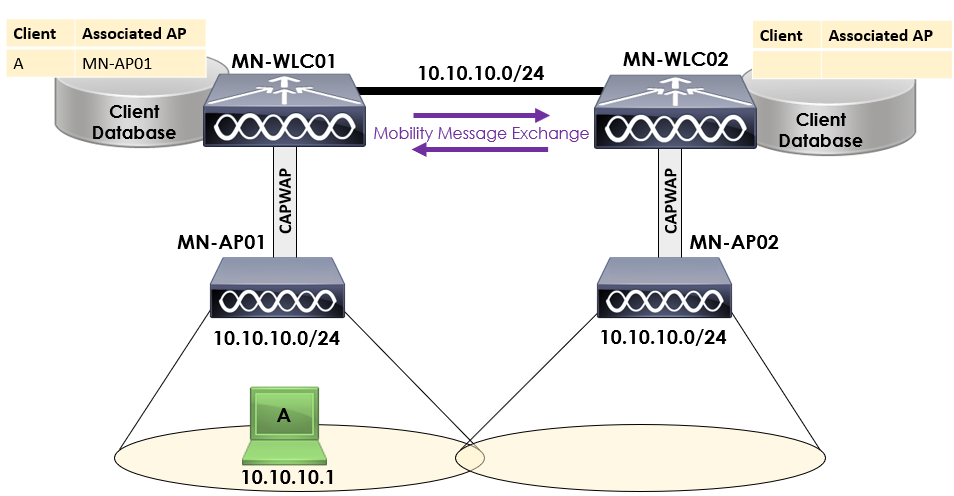
In our topology above, we have two APs associated to two controllers. MN-AP01 is associated to MN-WLC01 and MN-AP02 is associated to MN-WLC02.
Both controllers are located within the same network, 10.10.10.0/24. Our client, client A is associated to MN-AP01 with an IP address of 10.10.10.1.
As before, both our controllers each maintain a client database that contains how to reach the clients associated to it.
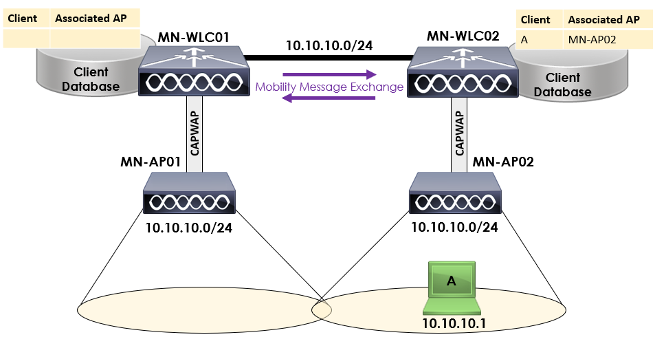
When Client A roams from MN-AP01 to MN-AP02, an intercontroller roam has taken place. Importantly, as both controllers and AP is operating on the same layer 2 subnet, this is classed as an intercontroller layer 2 roam.
When this occurs, the following actions take place:
1. Mobility messages exchanged between controllers.
2. Client database entry for Client A is moved from MN-WLC01 to MN-WLC02.
As both controllers are located within the same subnet, the client can keep the original IP address (10.10.10.1) without having to request a new IP address.
Intercontroller Roaming – Layer 3
As we discussed previously, an intracontroller roam occurs when a client roams between APs associated to two different WLCs. The big difference for the roam to be classed as a layer 3 intercontroller roam, both controllers will be on separate subnets.
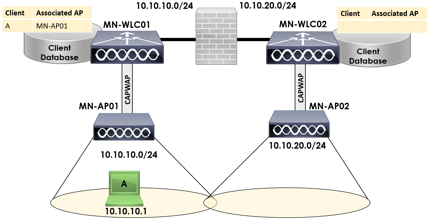
In our topology above, we have two APs associated to two wireless controllers. MN-AP01 is associated to MN-WLC01 and MN-AP02 is associated to MN-WLC02.
Both WLCs are located within different subnets. MN-WLC01 is located in 10.10.10.0/24 and MN-WLC02 is located within 10.10.20.0/24.
What happens when Client A roams to MN-AP02? The IP it has whilst associated to MN-AP01 isn’t going to work. The client would have to request another IP address from a DHCP server and obtain a new IP address.
Can you imagine the disruption this would cause to a client? Especially for real-time applications.
Thankfully, Cisco has a trick for the client to roam seamlessly.
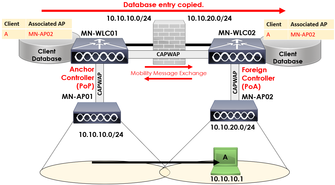
This time, when Client A roams from MN-AP01 to MN-AP02, a number of actions will take place;
1. Mobility messages exchanged between controllers.
2. Client database entry for Client A is copied from MN-WLC01 to MN-WLC02.
3. Controllers allocated either anchor or foreign role.
4. Controllers allocated either PoA or PoP roles.
Client A is now associated to MN-AP02, connected to MN-WLC02.
MN-WLC01 is then classed as the anchor controller
for Client A. The controller that Client A roams to (MN-WLC02) is then classed as the foreign controller.
The anchor controller role is allocated to the original controller that client A associated to; MN-WLC01.
The foreign controller role on the other hand is allocated to the controller Client A is currently associated to. In this case, MN-WLC02.
Want to know the great thing? Client A will keep the IP address it had whilst associated to MN-AP01; 10.10.10.1.
You might be thinking, how is that possible?
A CAPWAP tunnel is created between MN-WLC01 and MN-WLC02 that will be used to tunnel all traffic from Client A back to MN-WLC01. This allows Client A to retain it’s IP address and operate on a foreign controller.
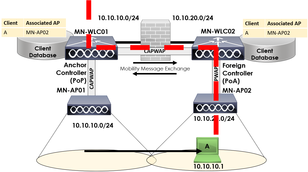
Traffic to and from Client A is then routed back to the anchor controller via the CAPWAP tunnel between MN-WLC01 and MN-WLC02.
You’ll notice two additional bits of information on our topology that we’ve not discussed yet:
During layer 3 roams, there are two additional roles that are introduced, PoA and PoP.
The PoA (Point of Association) identifies the controller/AP where the client is currently associated. In our example above, client A is still associated to MN-WLC02 so this is the PoA.
It’s important to note that the PoA role moves with the client as it roams. As such, if we had another controller named MN-WLC03 and our client roamed to this, MN-WLC03 would then take the PoA role for the client.
The other role, PoP (Point of Presense) is used to refer to the controller where the client can be accessed. A common mistake is to think of this role of the controller first associates to, however as you’ll see in the next section – this is incorrect.
In our example, MN-WLC01 is the PoP as Client A can be accessed via 10.10.10.1 through MN-WLC01.
Auto-Anchor Mobility
Now that we’ve covered the concept of anchor and foreign controllers, let’s take a look a look at the final roaming concept; Auto-Anchor.
What auto-anchor allows us to do is anchor a WLAN to a specific controller within our network. The most common use case for this is guest access.
Allowing guests on our corporate network is a big no-no. Instead, we can force all guests connecting to the network to be forced onto a specific wireless controller located within a DMZ network.
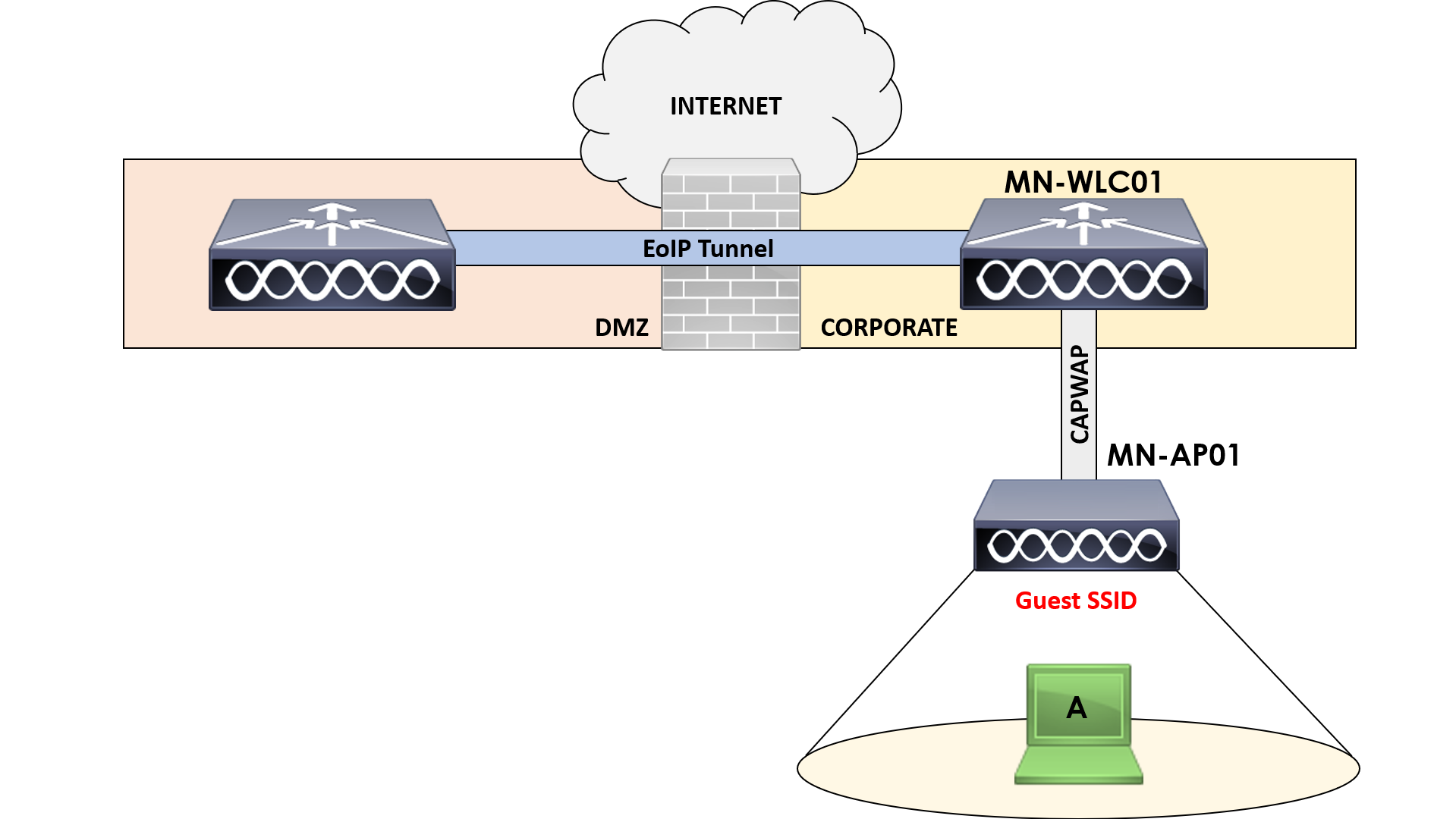
In our topology above, we have an AP; MN-AP01 associated to MN-WLC01. In addition to this, we’ve also got a separate WLC; MN-WLC02. This controller is located in our DMZ network behind our firewall.
Client A connects to our Guest SSID advertised via MN-AP01. With auto-anchor mode, all of the guest traffic from Client A will be tunnelled to MN-WLC02 via an EoIP tunnel.
From here, the guest traffic is then piped directly out to the internet.
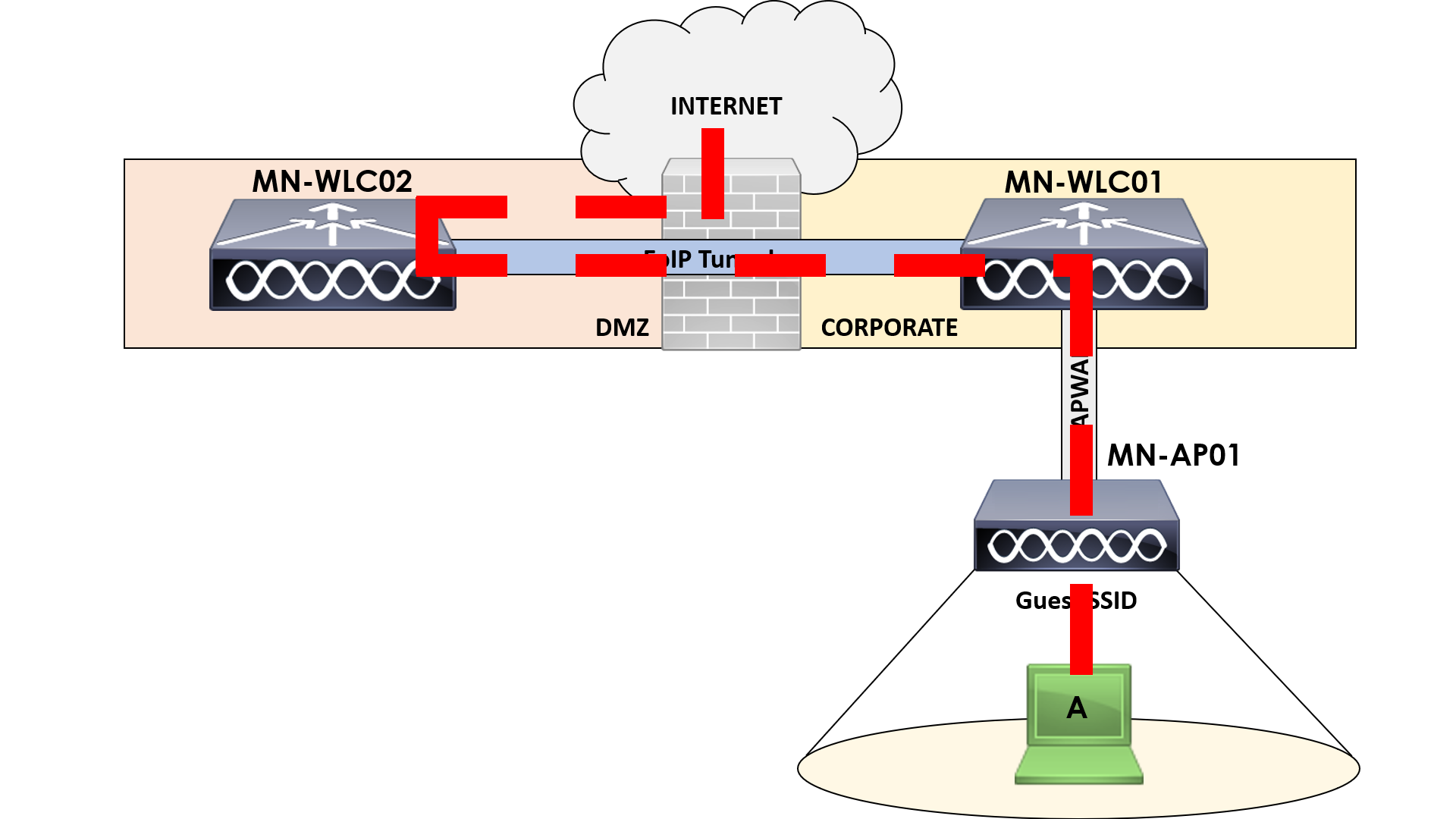
I’ve outlined this in the figure above to help you understand better. All traffic from Client A is tunnelled to our WLC in the DMZ (MN-WLC02). This way none of the traffic can touch our corporate network and can be sent straight out to the internet.